Some aspects of design, manufacture, use and maintenance of slow solid rotors - Part I
Abstract
Purpose of this publication is to address some cross-disciplinary aspects of design, manufacture, use and maintenance of a broad class of slow rotors – solids that rotate at relatively low speeds. “Low speed” is here loosely defined as rotation below 700 to 900 rpm, a flexible boundary perhaps pending mostly on dimensions, centrifugal forces and resulting stresses. Behaviour in applications, failure modes and conceptual development of multipurpose testing methodology are matters of special importance, systematic review of which will reveal new avenues leading to better holism in design, manufacture use and maintenance. Authors believe that there are significant differences between the classes of "slow rotors" and "faster rotors". The pertinent differences and attributes affect the design, manufacture, use and maintenance to the extent demanding a holistic review of relevant knowledge.
CONTENTS
Part I
INTRODUCTION
APPLICATIONS AND PERFORMANCE
ASPECTS OF MATERIALS
Part II
ASPECTS OF MECHANICAL AND ELECTRICAL DESIGN
ASPECTS OF MANUFACTURE
ASPECTS OF MAINTENANCE AND ENVIRONMENTAL SUSTAINABILITY
FUTURE
CONCLUSIONS
References
INTRODUCTION
A number of publications, [1– 65] was reviewed based on the keywords “rotating machinery”, “rotary / journal / rolling / antifriction / sleeve / sliding bearings”, “rolls”, “rolling-sliding”. Important confinements include focusing on solid engineering objects, “mechanical components” that revolve at relatively low speed. In this publication a solid part that revolves relatively to a reference system is termed a rotor (a definition consistent with [17 – 19]). Diversity of examples – windmill components, rolling mill rolls, drum mixers, tram wheels, ore crushers, ball mills, rotating furnaces, bulldozer, twin-roll caster – should not hinder an impetus to distinguish their common features.
Authors are aware of importance of academic categorization of knowledge into specialist sub-domains of academic disciplines, each with their special terminology and concepts. This systematic approach has certainly brought in the tides of progress in understanding crucial aspects of design, manufacture, use and maintenance of rotating machinery. However, the overemphasised enclosure within formal domains, has also raised undesired barriers. Recent trends in science in general favour the despecialization of knowledge and collaborative communication between initially separated disciplines.
The strategy adopted in this study is that the relevant phenomena should be addressed using a cross-disciplinary approach. At the same time, well established nomenclature and concepts based on Chemistry, Physics and Mathematics, are referred to. Moreover, this review exploits the advanced scientific definitions from the fields such as thermal sciences, theory of plasticity or electronics, e.g. contact mechanics, stochastic concepts, fluid dynamics, thermal phenomena and tribology. These concepts and theories are used as explanatory and investigatory means within the framework of design, manufacture, usage and maintenance.
Looking at the rotating phenomena within the real systems provides an opportunity for translating the experience by visualizing eloquent analogies. Analyzing the construction and operation of an existing system is in particular useful for design tasks. Each of the design stages shown in Fig 1 can be compared to similar scenarios observed in already existing configurations.
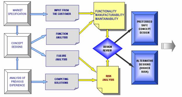
Fig 1: An example of a design algorithm
Rotors (solids of revolution) which are incorporated in various engineering systems can be sub-divided into “working rotors” and “facilitating rotors”. For example, motion of an industrial bogie along the rails is actuated by means of wheels; wheels themselves are “working rotors” connected to the bogy frame via bearings, which are “facilitating rotors”. Bogie driving machine has, in addition, the force transmitters, e.g. gears, which are also classified here as “facilitating rotors”. Parts that are joined to working rotors (and usually rotate with the same rpm) may be considered to be supporting parts of working rotors.
Further criteria for classification of solid rotors may include:
- application
- failure modes
- design (including materials)
- manufacture
- maintenance, etc.
From the viewpoint of application and maintenance, one of key questions is: how important is function of the observed rotor, i.e. how significant are consequences in the case of rotor failure or function degradation? It follows that increasing investments in manufacture of a rotor is justified in proportion to it criticality, and so are the investments addressing reliability, availability, replacement and maintainability.
Failure modes of rotors span from purely stress-strain relations, to purely chemical deterioration. Between these “extremes” there are complex mixed modes due to additional effects such as surface wear, thermodynamic effects and intrinsic aging of rotor material.
Important question is whether the system function and life are limited due to failure of facilitating rotor or because of failure of (supporting part or working part) of a working rotor. Many applications comprise both slow and fast rotors engaged in mutual contact.
In order to systematize factors and indicators of performance, differences between “slow rotors” and “faster rotors” should be addressed. Inasmuch as defining these differences will provide useful indications, a more detailed scrutiny and classification of slow rotors will enable focusing on most promising avenues towards improvements. It is important to note that improvements may be found in design (including the selection of materials), in modes of manufacture and ways of application, as well as in the maintenance techniques and methods used to analyse (simulate) relevant category of phenomena. Interfaces of rolling-sliding contact are intensely investigated within the fields such as contact mechanics, thermal sciences and tribology.
At a first glance, it seems only logical to assume that the intrinsic centrifugal forces must be less significant in the case of low rpm when compared to high rpm, given the same other conditions. When centrifugal force introduces significant internal tension stresses, the overall loading stresses may shift partly or completely into the field of tension. Most of the time centrifugal stresses play role only for very large number of revolution (e.g. 20,000 rpm).
Figures 2 and 3 present stresses at an extreme point on the rotor surface, e.g. a point on the working surface of a roll – tool in a cold rolling mill – which periodically comes in contact with the counterbody (a solid metal formed by rolling). When tool (roll) starts rotation, centrifugal stresses in that point will reach corresponding level. At the same time, processed solid metal enters the deformation zone, and contact stresses (in the observed point) will reflect rotations of the roll. Note that the average value of total stresses in this point is elevated due to the presence of centrifugal stresses. If we ignore running-in stage, as well as the initial peak stresses and subsequent depreciation in stresses, it can be identified some average period during which the stress fluctuations follow certain stable frequency. In some configurations this period is quite significant and relevant attributes will present dominant factors.
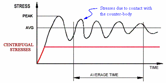
Fig 2: A scenario of cyclic stresses for fast rotors; combined centrifugal and contact stresses oscillate within a tensile domain
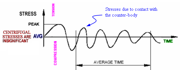
Fig 3: A scenario of cyclic stresses for slow rotors; the Bauschinger effect is significantly enhanced
Many materials and geometries are sensitive to tensile stresses and loading scenarios that include dynamic fluctuations of stresses.
The number of stress cycles per unit time certainly presents significant difference between slow and fast rotors. Rotating elements of machines are often designed to "last" several millions of cycles of fluctuating load and if machine rotates faster this is achieved after much shorter time (e.g. according to Goodman diagram). From the point of view of fatigue, a steel rotor can be made to last indefinitely (at least theoretically) if the stress is below endurance limit; however bearing in mind other modes of deterioration such fatigue endurance may present a waste. Also, aluminium alloys and some other nonferrous alloys do not have endurance limit therefore the fatigue will occur within a short period even at very small loads for rotors made of such materials.
Other configurations will be more affected by the peak stress. Although it appears sensible to anticipate lower impact forces in slow rotors, when compared to faster rotors, there are some special limitations. A typical example is so called “ball mill”, where solid hard spheres are free to float inside a drum. The speed of drum rotation is actually set to lift the spheres by centrifugal force for a fraction of drum diameter (free fall then produces the crushing effect on softer material introduced into drum). Therefore, the impact forces would increase with rpm only up to a certain level of rpm, above which spheres would stick to walls. However, as long as these special cases are identified, a general rule may be utilized as follows: impact increases with rpm.
Since the gravity force increases with dimensions, slow rotors generally have insignificant influence of centrifugally induced stresses (exceptionally large hollow rotors require additional analysis in order to evaluate significance of centrifugal acceleration).
Another criterion for differentiating slow and fast rotors is based on the fact that gyroscopic effects decrease with the speed.
In many applications contact temperature is a factor of considerable significance. Heat transfer presents further important criterion for differentiating between slow and fast rotors. Heat transfer related to local contact with counter body is enhanced, while friction generated heat is debilitated in the case of slow rotors compared to fast rotors. Generally, in high-speed rotors overheating due to friction across the sliding surfaces is often encountered. This problem will not be emphasized in slow rotors, as long as the relation between the dimensions and peripheral speed provides beneficial conditions for removal of friction generated heat.
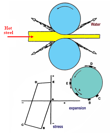
Numerous applications (e.g. manufacturing by rolling process, direct forming by casting between the twin rolls) involve contact of rotors with a counteragent at an elevated temperature (> 1000 oC). Figure 4 depicts a hysteresis diagram of the stress strain levels that occur in the tool surface due to the temperature fluctuations.
An analysis of the interfacial processes taking place during the contcat of the rotors with fluids requires addressing the disciplines such as fluid dynamics and rheology. As the counteragent attributes shift from an ideal rigid solid, via the elastic and plastic continuums, towards the attributes of the fluids, the interfacial phenomena shift from an impact, bulk elastoplastic response and abrasion, towards erosion, corrosion and electromagnetic interactions.
The significance of the third agent – the coolants and lubricants that are appearing across the interface in various states of matter – must not be neglected. As an example, consider the case of a special traction lubricant that stiffens as the load is applied thus increasing the tractive effects. [20]
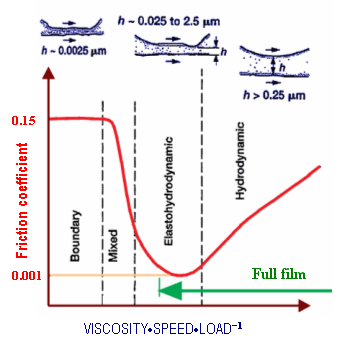
The conditions met in the case of the appearance of boundary lubrication present a further important criterion for distinguishing families of the slow rotors and the fast rotors, Fig 5.
Fig 5: The Stribeck, Gumbel, McKee, Petroff and Hersey consensus: friction as function of viscosity-speed-load parameter [24 – 27]
A number of researchers have observed that wear (in particular abrasion) decreases with increase in sliding velocity, up to 0.3 m/s [28 - 30]. This observation is in agreement with finding that slow rotating machinery tends to exhibit self-exited vibrations often called chatter, and frequently recognized by unpleasant squeaky noise, due to onset friction induced. The cause of the vibrations is the friction force. It has been observed that friction force decreases with the increase in sliding velocity. This phenomenon takes place because, for a small amplitude, the oscillatory systems display amplification – dumping in which dumping factor is equal to the negative slope of the friction curve and thus term "negative damping" [31]. The examples of the chatter in the machine elements, given by V Castelli in Marks' Standard Handbook for Mechanical Engineers, are the "rubber stern tube ship bearings at low speed and oscillating rolling element bearings especially if they are supporting large flexible structures such as radar antennas". The amplitude of vibration increases until the nonlinear effects in the machine cause stable limit-cycle vibrations [32] , where energy transferred from the machine sustain vibration at the specific energy level [33]. It is interesting to notice that these self excited vibrations are close to the natural frequency of the system.
At higher sliding or rolling speeds, negative slope of the friction force decreases in absolute values reaching zero or even positive slope, that cannot supply energy to cause chatter (i.e. damping is zero or positive) [31 - 34]. This is in good agreement with findings that at higher sliding velocities, friction generated heat may cause significant increase in friction between unlubricated surfaces.
Further feature distinguishing slow and faster rotors is related to fact that accelerometers sensitivity is linearly increasing with increasing rotational speed, while vibration sensors based on velocity or displacement amplitude show better sensitivity at lower frequencies.
For continuation please contact sead.spuzic@unisa.edu.au